LibreLane
LibreLane is a powerful and versatile infrastructure library that enables the construction of digital ASIC implementation flows based on open-source and commercial EDA tools.
This tutorial will teach you how to implement a simple counter using LibreLane, how to view your design, and what the run/ directory is used for. The last section provides further resources on LibreLane.
But first, take a look at the LibreLane repository and the documentation in order to install LibreLane through one of the many options provided. The recommended option is to install LibreLane through Nix.
Once you have successfully installed LibreLane, you can start with the first step below.
Creating the Files
At a minimum you need to provide your RTL files to LibreLane, as well as a LibreLane configuration. Create a new folder in which you will put the following files.
Create counter.sv with the following content:
// A simple 8-bit counter

module counter (
	input  logic       clk_i,
	input  logic       rst_ni,
	output logic [7:0] count_o
);

	always_ff @(posedge clk_i) begin
        	if (!rst_ni) begin
            	count_o <= '0;
        	end else begin
            	count_o <= count_o + 1;
        	end
	end

endmodule
This is a simple 8-bit counter with clock and reset.
Create config.yaml with the following entries:
DESIGN_NAME: counter
VERILOG_FILES: dir::counter.sv
CLOCK_PORT: clk_i
CLOCK_PERIOD: 10 # 10ns = 100MHz
This is the LibreLane configuration which tells LibreLane where to find the source files and how to configure the flow.
The DESIGN_NAME is the top-level module of your design, in this case counter. VERILOG_FILES specifies all source files for your design. This can be a list of files, or even a wildcard such as dir::path/to/my/files/*.sv.
CLOCK_PORT is the, well, clock port of your design and CLOCK_PERIOD specifies at which clock period the design should operate at. LibreLane will use this information to run CTS (Clock Tree Synthesis) and set up the default SDC (Synopsys Design Constraint) file. For larger designs it could happen that the 100MHz are not achievable and LibreLane will report an error.
Running the Flow
Running the flow is as simple as invoking LibreLane and specifying both the PDK and the configuration file:
librelane --pdk ihp-sg13g2 config.yaml
This command invokes LibreLane with the ihp-sg13g2 PDK and the config.yaml configuration file.
By default LibreLane will manage the PDK for you. That includes selecting the right version of the PDK and downloading it. The default PDK_ROOT (the directory where all PDKs are stored) is in your home directory under ~/.ciel. Why ciel?
Ciel is a version manager and builder for open-source PDKs. LibreLane uses ciel to manage the PDK that you have selected. By default LibreLane uses sky130A as the PDK, thus we changed it using --pdk ihp-sg13g2.
If you want to select a specific version of a PDK, you can tell LibreLane to do so with --manual-pdk. LibreLane will then use the PDK_ROOT and PDK environment variables, or the --pdk-root and --pdk arguments to find the PDK.
LibreLane runs the default Classic flow which is the right choice for most designs. The flow consists of individual steps such as Yosys.Synthesis to synthesize your design, OpenROAD.Floorplan to create the boundaries of your design, OpenROAD.GlobalPlacement to place the standard cells (globally), and more.
After the flow has completed, LibreLane gives you a summary of potential errors, antenna violations, as well as DRC and LVS errors.
By now, LibreLane should be finished implementing the counter. You should see the following green checkmarks:
* Antenna
Passed ✅

* LVS
Passed ✅

* DRC
Passed ✅
Along with maybe some warnings (which can be ignored in this case).
Congratulations! You have implemented your first design 🎉
View Your Design
It would be quite boring if that was all. Luckily we can visualize the design using OpenROAD GUI and KLayout.
Using OpenROAD GUI
OpenROAD is used by LibreLane to perform the physical design steps. It also has a GUI with which you can view and debug a design.
To open OpenROAD GUI, simply run the same command again with some additional arguments:
librelane --pdk ihp-sg13g2 config.yaml --last-run --flow OpenInOpenROAD
--last-run tells LibreLane to reuse the last run folder with the latest state (we will talk about the run folder shortly). And --flow OpenInOpenROAD tells LibreLane to use the OpenInOpenROAD flow instead of the Classic flow for implementing designs.
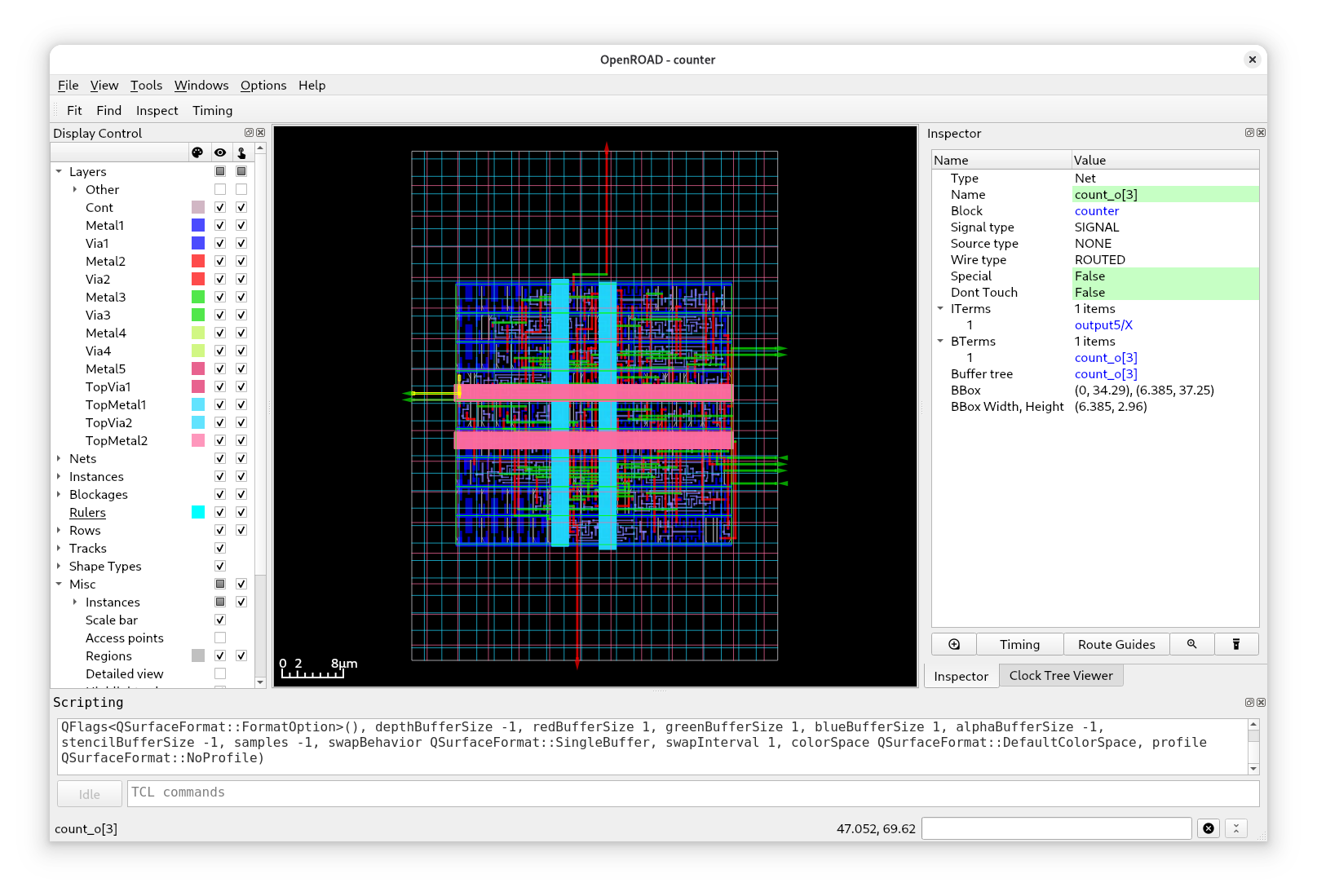
You should see a similar view as in this image. In the center is your design with the display control on the left and the inspector on the right.
Take your time to discover all the features of OpenROAD GUI: you can disable certain layers, select cells, enable heatmaps and so on. If you build larger designs, you will spend a lot of time in the GUI debugging certain problems.
One important point is the clock tree of your design. View it using the “Clock Tree Viewer”. If not open, you can enable it in the top menu at “Windows” → “Clock Tree Viewer”.
Click on “Update” and you should see the following:
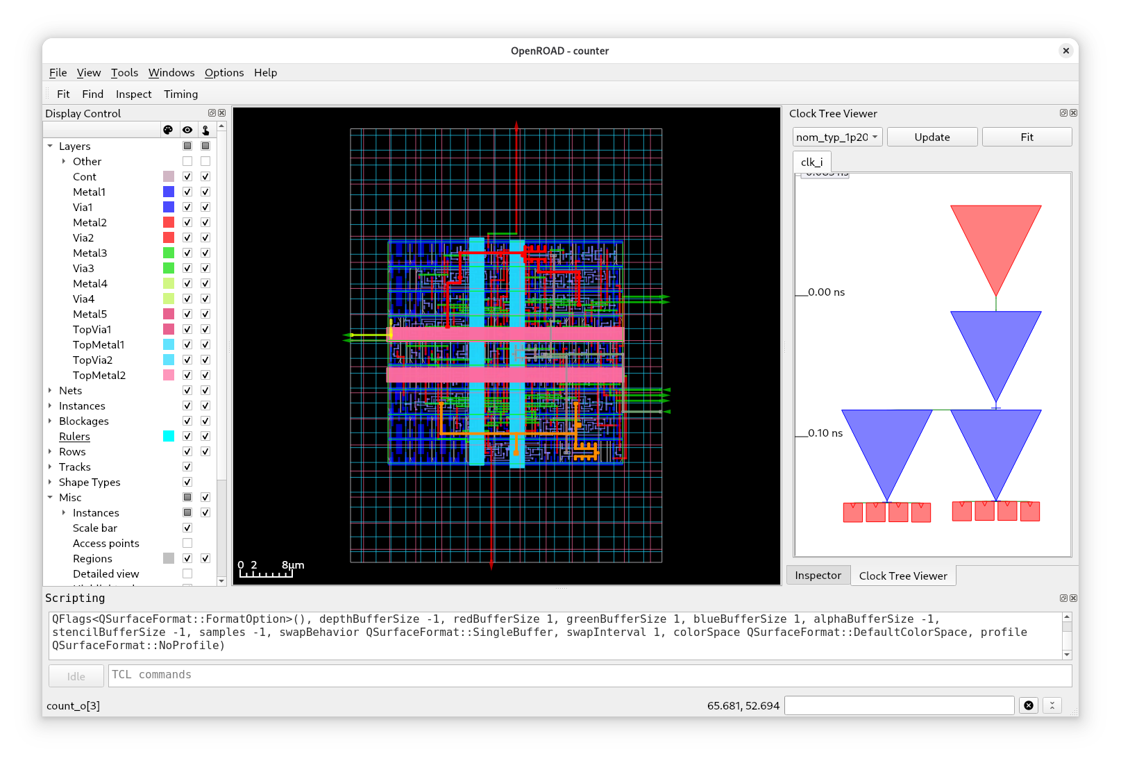
Well, there’s not much to see here because the design is so small. At the top is the root buffer (red triangle) followed by three other buffers (blue triangles). The leaves of the clock tree are connected to 8 flip-flops, one for each bit of the counter. Notice how the clock traces in your design are now in color.
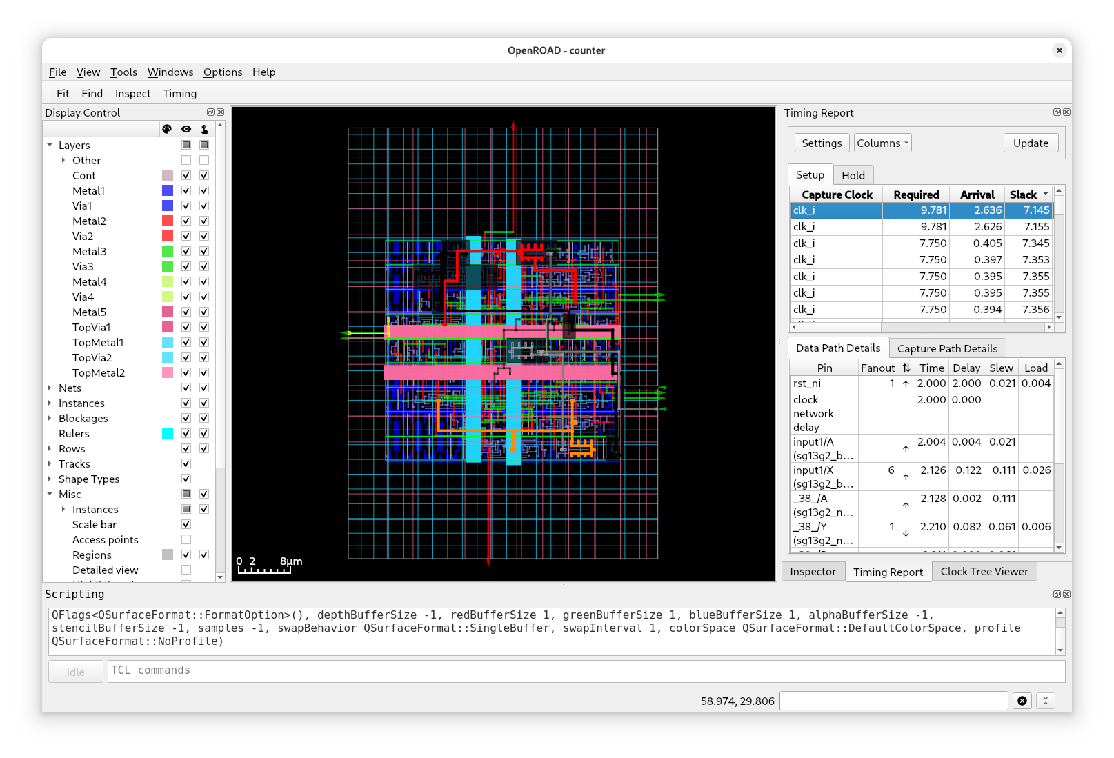
You can also view the timing paths of your design, open the “Timing Report” if not yet open: “Windows” → “Timing Report”.
Click on “Update” and you can select a path:
Tip: If you want to export your design in high resolution on a white background, just set “Display Control” → “Misc” → “Background” to white and run
save_image image.png -width 4096in “Scripting”. For the clock tree you can use:save_clocktree_image.
Using KLayout
While OpenROAD GUI opens the ODB (OpenDB) of your design, KLayout will load the LEF/DEF or the GDS of your design, containing all geometry information.
To open your design in KLayout run:
librelane --pdk ihp-sg13g2 config.yaml --last-run --flow OpenInKLayout
This should open the following window:
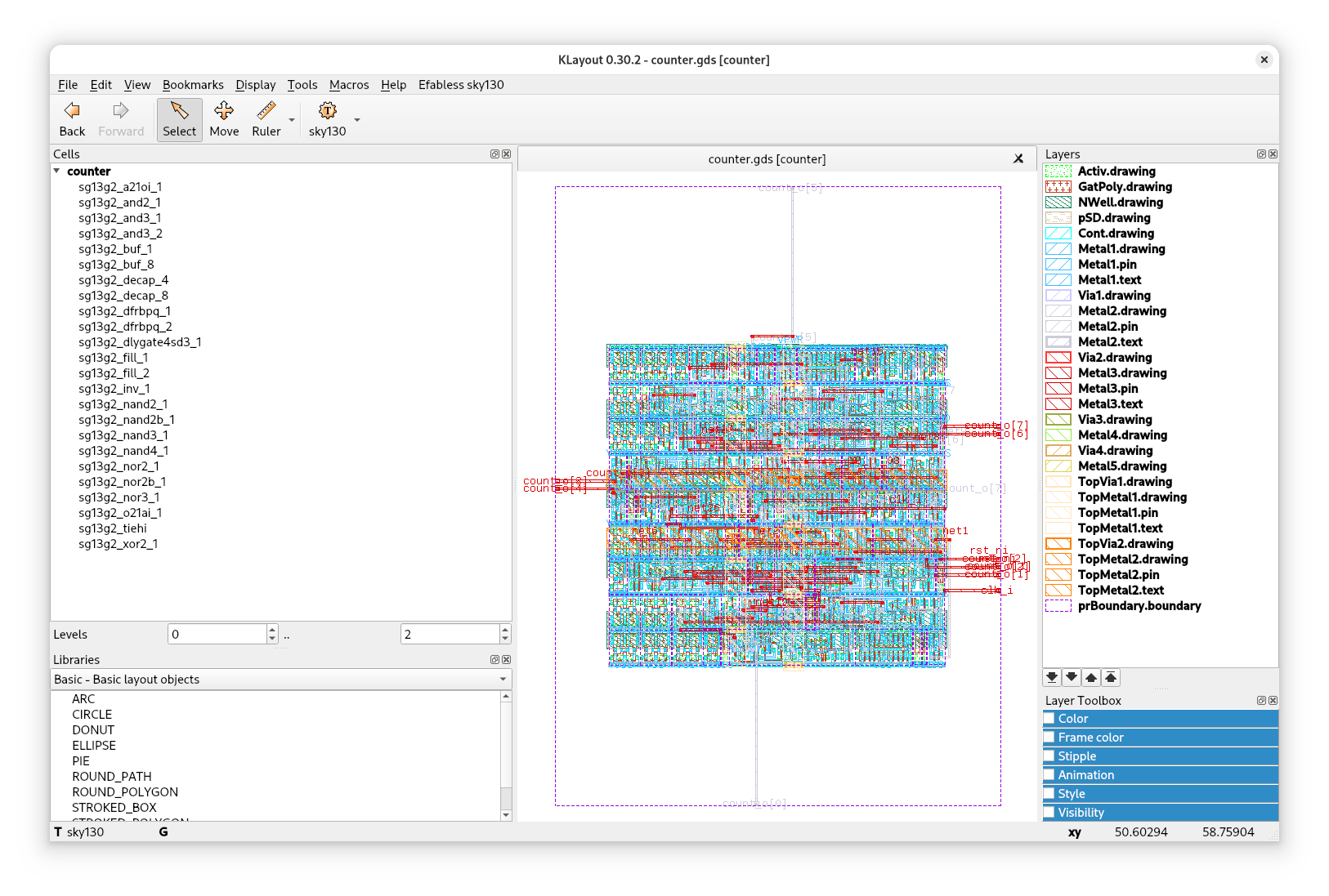
In the center you can see your design, on the left a hierarchy of the cells, and on the right the layers of ihp-sg13g2.
These are the layers (at least many of them) which are then sent to the foundry for manufacturing.
In KLayout you could also run DRC (Design Rule Check) and LVS (Layout Versus Schematic), however, LibreLane does this already for you as the final implementation checks.
Try to zoom in on the cells, select individual layers, and take measurements using the ruler.
Discover the run/ Directory
You may have noticed that a new directory was created while LibreLane was running: the run/ directory.
If you take a look inside, you will see a number of run tags, such as RUN_2025-10-31_09-25-56, for each run you started.
Within these runs tags are the flow log, the error and the warning file, as well as directories for each step executed.
For example, if you open 13-openroad-floorplan, you will find the input state (state_in.json), the output state (state_out.json) and a number of artifacts such as the .odb file of your design or the unpowered and powered netlist (.nl.v and .pnl.v).
Each step takes the input state, operates on it (possibly creating new files), and finally creates the output state.
For debugging purposes, it is very useful to have a look at the directory of the step that is failing.
Further Resources
And that was it for this example.
You have successfully implemented a counter using LibreLane! However, this is just the beginning. There are many advanced topics that are not covered by this tutorial, for example:
Customize your design with configuration variables
Controlling the flow (run to a step, start from a step, skip steps)
Integrating other macros in your design (e.g. foundry provided SRAM macros)
Using the LibreLane API
Full Chip Design
LibreLane provides usage guides and documentation about the available variables, the API, and how to customize flows at the LibreLane documentation: https://librelane.readthedocs.io
If you would like to create a full chip design with LibreLane, please continue with: Full Chip Designs With Librelane.