1. Filler Generation
Dummy metal fill ensures uniform metal density distribution across the integrated circuit layout. In regions with sparse metal features, the metal density differs significantly from densely routed areas. This non-uniformity adversely affects chemical-mechanical polishing (CMP) processes, resulting in over-polishing (dishing) in low-density regions and under-polishing in high-density regions. These surface variations degrade subsequent layer quality and can lead to manufacturing defects, reduced yield, and reliability concerns. Dummy metal fill addresses this issue by inserting electrically inactive metal shapes in sparse regions to achieve uniform density distribution, thereby ensuring consistent CMP performance and improved fabrication outcomes.
Note
It is mandatory to have a sealring in the design which can be dragged and dropped from the libraries menu in klayout left pane.
2. KLayout
The filling process can be executed either using a menu item from KLayout’s GUI or the command line using the provided Python script.
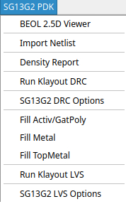
The SG13G2 PDK menu has several items related to the fillers. The Fill Activ/GatPoly, Fill Metal and Fill Top Metal
will generate filler shapes on the corresponding layers. The Density Report will calculate the densities and report it in the terminal
window.
As an alternative one can use the python script for generating fillers:
klayout -n sg13g2 -zz -r $PDK_ROOT/$PDK/libs.tech/klayout/tech/scripts/filler.py -rd output_file=./design_filled.gds design_nofill.gds
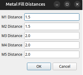
2.1. Controlling Metal Filler Densities
The adjustment of the Metals 1-5 densities can be changed by modification of distances between the metal fillers, where the minimal
spacing between metal fillers is 0.42um.
In order to adjust metal filler densities using CLI interface, modify the following scripts:
$PDK_ROOT/$PDK/libs.tech/klayout/tech/scripts/macros/sg13g2_filler_Metal.lym
$PDK_ROOT/$PDK/libs.tech/klayout/tech/scripts/macros/sg13g2_filler_TopMetal.lym
Within these scripts, the width, length, and distance parameters can be adjusted to achieve the desired density levels. Ensure that all modifications comply with DRC rules for filler cell sizing and separation, as specified in sections 5.18 and 5.23 of the SG13G2_Layout_Rules_os.pdf document.
2.2. Verification
After applying the fillers, the first step is to verify that the desired density levels are met using the Density Report tool available in the SG13G2 PDK menu.
Note
When running minimal DRC checks in KLayout, AFil.g2 and M1-5Fil.h errors may appear for regions outside the design area where densities are calculated. These errors can be safely waived.
The final check is to run DRC with default options and make sure that Disable Denisty Check under Advanced options is not checked.
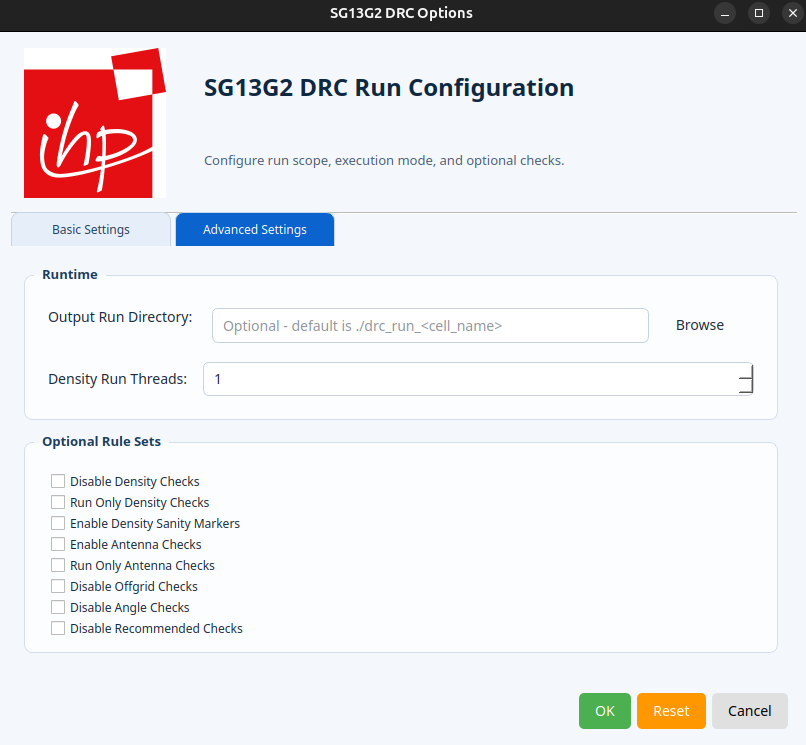
In order to speed up the process of density checking on large designs one can check Run Only Density Check and increase number of Density Run Threads.
Warning
The density checks are part of the rejection test during the submission process. If your desing does not meet the required values it will be rejected.
3. gdsfill
gdsfill is an open-source tool for inserting dummy metal fill into semiconductor layouts. It helps designers meet density requirements and prepare GDSII layouts for manufacturing by analyzing, erasing, and generating dummy fill patterns across multiple layers. The tool is designed to integrate easily into existing design flows and ensures reproducible, automated preparation of layouts before tape-out.
For more information visit the official GitHub page.
3.1. Installation
gdsfill can be installed as a Python package. We recommend using a virtual environment to keep dependencies isolated.
$ python3 -m venv venv
$ source venv/bin/activate
 (venv) $ pip install --upgrade pip
(venv) $ pip install gdsfill
3.2. Density
This command calculates the utilization per layer and prints the values. It is useful to check layer density before and after running the fill process:
gdsfill density <my-layout.gds>
3.3. Erase
If a layout already contains dummy fill, or if previous fills should be removed, this command erases all dummy metal fill from a layout:
gdsfill erase <my-layout.gds>
3.4. Fill
To insert dummy metal fill into all supported layers of a layout, run:
gdsfill fill <my-layout.gds>
By default, gdsfill creates a temporary directory for intermediate data.
Use --keep-data to retain all generated files in a directory called gdsfill-tmp:
gdsfill fill <my-layout.gds> --keep-data
If you only want to simulate the process without modifying the layout file, use --dry-run:
gdsfill fill <my-layout.gds> --dry-run
3.5. Custom Configuration
By default, gdsfill inserts dummy metal fill into each layer using predefined parameters. To apply different parameters or restrict fill to specific layers, you can create a custom configuration file.
The following example config inserts fill only into TopMetal1 and TopMetal2:
PDK: ihp-sg13g2
layers:
  TopMetal1:
    algorithm: Square
    density: 60
    deviation: 1
  TopMetal2:
    algorithm: Square
    density: 60
    deviation: 1
Note
An example config file is available in the GitHub project.
To use a custom config file, pass it with --config-file:
gdsfill fill <my-layout.gds> --config-file <my-config-file.yaml>